TRANSDUCERS
A measuring device which measures and converts nonelectrical variable into electrical variable is known as transducer. Transducers are classified into several types. However, these can be categorized into
Five types. They are,
1. Classification on the Basis of Transduction Principle Used
This classification is done depending on the transduction principle i.e., how the input variable is being converted into capacitance, resistance and inductance values. (These are named as capacitive transducer, resistive transducer and inductive transducer respectively).
Eg: Microphone (for capacitive transducers)
Resistance Thermometer (for resistive transducers)
Magnetostriction gauge (for inductive transducers)
2. Active and Passive Transducers
Active Transducer
The transducer which does not requires any external excitation to provide their outputs are referred as active transducer.
Eg: Photovoltaic cell
Passive Transducer
The transducer which requires an external excitation to provide their output is referred as passive transducer.
Eg:
1. Capacitive transducers.
2. Resistive transducers.
3. Inductive transducers.
3. Analog and Digital Transducers
Analog Transducer
The transducer which produces their outputs in analog form or a form which is a continuous function of time is referred as analog transducer.
Eg: Thermistor
Digital Transducer
The transducer which produces their outputs in digital form or a form of pulses is referred as digital transducers.
Eg: Turbine Meter
4. Primary and Secondary Transducers
Primary Transducer
The transducer which sends the measurement and converts them into another variables (like displacement, strain etc.) and whose output forms the input of another
transducer is called as primary transducer.
Eg:Strain Gauge
Secondary Transducer
The transducer which converts the output of first transducer into an electrical output called secondary transducer.
Eg: LVDT
5. Transducers and Inverse Transducers
Transducers
A measuring device which measures and converts nonelectrical variable into electrical
variable is known as transducer.
Inverse Transducer
A measuring device which measures and converts an electrical variable into
nonelectrical variable is known as inverse transducer.
Eg: Piezo-electric crystal
1] RTD
· RTD is made up of metals
· Metals have Positive Temperature Coefficient (PTC) of resistance. Hence ,the resistance of RTD increases with an increase in temperature and decreases with a decrease in temperature.
· The resistance temperature characteristics of RTD's are linear.
· It is less sensitive to temperature compared to thermistor.
· But, it has-a wide operating temperature range i.e., - 200 to +650°C.
· RTD's are relatively larger in size.
· They are costlier.
· They have low self resistance.
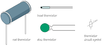
2] THERMISTOR
· Thermistor is made up of semiconductor materials
· Semiconductor materials have Negative Temperature Coefficient (NTC) of resistance. Hence, the resistance of a thermistor decreases with an increase in temperature and increases with a decrease in temperature.
· The resistance temperature characteristics of thermistor are highly nonlinear.
· It has large temperature coefficient of resistance i.e. It is highly sensitive to temperature.
· It has low operating temperature range compared to RTD i.e., -100 to + 300°C.
· Thermistors are small in size.
· They are available at low costs.
· They have high self resistance. Thus, they require shielding cables to minimize
interference problems.
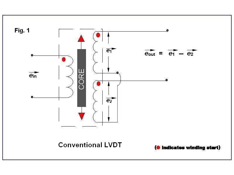
3] LVDT
· Linear Variable Differential Transformer (LVDT) consists of one primary winding (P)
and two secondary windings (51 and S2).with equal number of turns wound on a
cylindrical former.
· The two secondary windings are connected in series opposition and are placed
identically on either side of primary winding to which an AC excitation voltage is
connected.
· A movable soft iron core is placed within the cylindrical former.
· When the displacement to be measured is applied to the arm of the core, the LVDT converts this displacement into an electrical signal.
· The operating principle of LVDT depends on mutual inductance.
· When the primary winding is supplied with A.C. supply voltage, it generates alternating magnetic field. Due to this magnetic field an alternating voltage will be induced in the two secondary windings.
· In the figure, e1 is the output voltage of secondary winding S1 and e2 is the output voltage of secondary winding S2 .In order to get single differential output voltage two secondary windings are connected in series opposition. Thus the differential output voltage is given by,
e0=e1-e2
· When the core is placed symmetrically with respect to two secondary windings an equal amount of voltage will be induced in both windings. Therefore e1- e2 and the output voltage is '0'.Hence, this position is known as null position.
· Now if the core is moved towards up from null position, more magnetic field links with secondary winding S1, and small field links with secondary winding S2. Therefore more voltage will be induced in S1 and less in S2 ie, e1 will be larger than e2. Hence the differential output voltage is e0=e1-e2 and is in phase with primary voltage.
· But when the core is moved towards down from null position more magnetic field links with secondary winding S2 and small field links with secondary winding S1. Therefore more voltage will be induced in S2 and less in S1, i.e., es2 will be larger than es1. Hence, the differential output voltage is e0 = es2 – es1 and is 180° out of phase with primary voltage.
· Thus the output voltage e0 position of the core and hence the displacement applied to the arm of the core.
Merits
1. LVDT has good linearity i.e.. it produces linear output voltages.
2. It can measure displacements of very high range usually from 1.25mm to 250mm.
3. It has high sensitivity.
4. Since it produces high output, it does not require amplifier devices.
5. It has low hysteresis.
6. It consume less power (about < 1w)
Demerits
1. It is sensitive to stray magnetic fields.
2. Performance of LVDT is affected by variations in temperature.
3. It has limited dynamic response.
4. To provide high differential output, it requires large displacements.
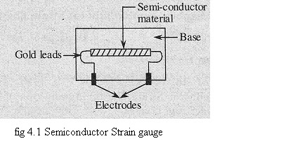
SEMICONDUCTOR STRAIN GAUGE
· A typical semiconductor strain gauge is formed by the semiconductor technology i.e., the semiconducting wafers or filaments of length varying from 2 mm to 10 mm and thickness of 0.05 mm are bonded on suitable insulating substrates (for example Teflon).
· The gold leads are usually employed for making electrical contacts. The electrodes are formed by vapour deposition.
· The strain sensitive elements used by the semiconductor strain gauge are the semiconductor materials such as silicon and germanium.
· When the strain is applied to the semiconductor element, a large of change in
resistance occur which can be measured with the help of a wheatstone bridge.
· The strain can be measured with high degree of accuracy due to relatively high change in resistance.
· A temperature compensated semiconductor strain gauge can be used to measure small strains of the order of 10-6 i.e., micro-strain. This type of gauge will have a gauge factor of 130 ± 10% for a semiconductor material of dimension 1 x 0.5 x 0.005 inch having the resistance of 350 Ω.
Advantages of Semiconductor Strain Gauge
1. The gauge factor of semiconductor strain gauge is very high, about ±130.
2. They are useful in measurement of very small strains of the order of 0.01 micro-strains
due to their high gauge factor.
3. Semiconductor strain gauge exhibits very low hysteresis i.e., less than 0.05%.
4. The semiconductor strain gauge has much higher output, but it is as stable as a metallic
strain gauge.
5. It possesses a high frequency response of 1012 Hz.
6. It has a large fatigue life i.e., 10 x 106 operations can be performed.
7. They can be manufactured in very small sizes, their lengths ranging from 0.7 to 7.0
mm.
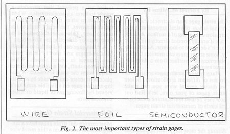
METAL FOIL STRAIN GAUGES
· In this type of strain gauges a metal foil is used to sense the applied strain. The
materials used for its construction are nickel, nichrome, platinum, isoelastic (nickel
+chromium + molybdenum), constantan (nickel + copper). The gauge factor and
characteristics of foil strain gauges are similar to the wire strain gauges.
· When a force or pressure is applied to the sensing element of metal foil strain gauge the physical dimensions of it will change.
· Since, the strain gauge element is pasted on its surface, the dimensions of the strain gauge changes due to which the resistance of the gauge changes.
· The measure of change in resistance will become the measure of applied pressure or force (this change in resistance of the gauge can be measured by connecting the gauge in any one of the four arms of balanced Wheatstone bridge).
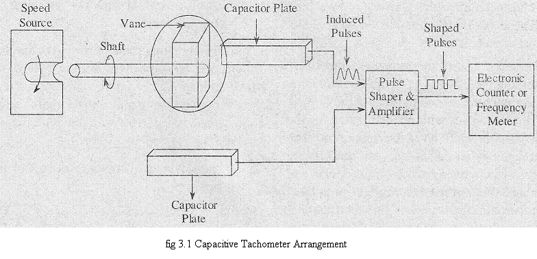
CAPACITIVE TRANSDUCERS
The main components of a capacitive tachometer arrangement are given as follows,
1. Fixed capacitor plates
2. A vane attached to one of the two ends of a shaft
3. A pulse shaper and amplifier circuit
4. An electronic counter or frequency meter.
· The vane is placed between the two fixed plates of capacitor and the free end
of the shaft is connected to the source whose angular velocity is to be determined.
· Therefore the shaft rotates along with the source, which in turn rotates the vane between the plates. Due to this the capacitance of the capacitor changes.
· For every rotation of the vane a change in capacitance
takes place and for every changed capacitance value, a voltage pulse is induced.
· The number of times the capacitance value changes per unit time gives the angular velocity of the rotating shaft.
· The induced pulses are applied to pulse shaper and amplifier circuit which shapes the pulses into accurate pulses and then amplifies the pulses. These shaped and amplified pulses are then applied to electronic counter which counts the number of pulses. The counted number of pulses directly gives the value of angular velocity.
Limitations:
1. Capacitive transducers are highly sensitive to temperature. Therefore any variation in
temperature affects the performance of the instrument.
2. High output impedance of capacitive transducers lead to loading effects
SOME FORCE SUMMING DEVICES
Force summing devices serve as primary transducers and convert the pressure applied at
the input into displacement, which then can be measured by means of secondary transducer. The lists of most widely used force summing devices are
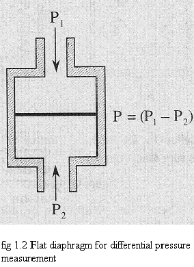
1. Diaphragms
· Any thin metal whose ends are fixed between two parallel plates is referred to as
diaphragm. It is one of the pressure measuring elements.
· The operating principle is the applied pressure is converted into proportional displacement.
· The materials used to make diaphragms are phosphor bronze, nickel, beryllium copper, stainless steel, etc.
· These can be available in flat or corrugated shapes.
Force summing devices serve as primary transducers and convert the pressure applied at
the input into displacement, which then can be measured by means of secondary transducer. The lists of most widely used force summing devices are
1. Diaphragms
· Any thin metal whose ends are fixed between two parallel plates is referred to as
diaphragm. It is one of the pressure measuring elements.
· The operating principle is the applied pressure is converted into proportional displacement.
· The materials used to make diaphragms are phosphor bronze, nickel, beryllium copper, stainless steel, etc.
· These can be available in flat or corrugated shapes.
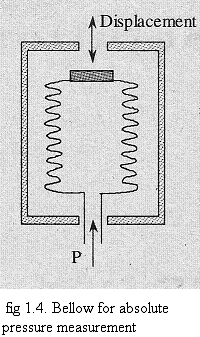
2. Bellows
· Bellows, the pressure measuring elements are formed by the series combination of
capsules.
· The working principle of bellows is same as that of diaphragms i.e., the applied
displacement is converted into proportionate mechanical displacement.
· The materials used to construct bellows are beryllium copper, brass, monel, stainless steel and nickel.
· Whenever the pressure to be measured is applied the sealed end of bellow suffers displacement.
· The generated displacement can be known by attaching a pointer scale arrangement to the sealed end or by transmitting the displacement to the secondary transducer.
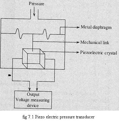
PIEZO-ELECTRIC TRANSDUCERS
· Piezoelectric pressure transducers depend on the principle of ‘piezoelectric effect’ i.e., when some pressure or stress is applied to the surface of the piezoelectric crystal, an electric charge voltage will be developed by the crystal.
· The materials used in the construction of piezoelectric crystals are quartz, Rochelle salt, dipotassium titrate, lithium sulphate, barium titanate etc.
· The pressure which is to be measured is applied to corrugated metal diaphragm. The
diaphragm deflects depending on the applied pressure, and this deflection signal is
transmitted to the crystal through the mechanical link.
· In other words, the pressure is applied to the crystal through the diaphragm and the link.
· When the crystal senses the pressure it will generate some voltage corresponding
to the applied pressure, and is measured in the output voltage measuring
device which is calibrated in terms of applied pressure.
Merits
1. Provides electrical output.
2. This transducer does not require any external power supply.
3. Size in small.
4. Rugged construction.
Demerits
1. It cannot be used for static pressure measurements.
2. The response will get affected by the variations in temperature.
3. In some cases it requires signal conditioning circuitry which is complex.
4. Cost is high
|
|
|
|
