Timers & counters
A timer is a special type of clock used to control the sequence of an event/process
8051 has two timers – Timer 0 and Timer 1
Both are 16 bit
Timer 0 receives clock signal from input T0
Timer 1 receives clock signal from input T1
TMOD – Timer ModeIt is a 8-bit register
Bits of this register have the following function:
GATE0 enables and disables Timer 1 using a signal brought to the INT0 pin (P3.2):
8051 has two timers – Timer 0 and Timer 1
Both are 16 bit
Timer 0 receives clock signal from input T0
Timer 1 receives clock signal from input T1
TMOD – Timer ModeIt is a 8-bit register
Bits of this register have the following function:
- GATE1 enables and disables Timer 1 by means of a signal brought to the INT1 pin (P3.3):
- 1 - Timer 1 operates only if the INT1 bit is set.
- 0 - Timer 1 operates regardless of the logic state of the INT1 bit.
- C/T1 selects pulses to be counted up by the timer/counter 1:
- 1 - Timer counts pulses brought to the T1 pin (P3.5).
- 0 - Timer counts pulses from internal oscillator.
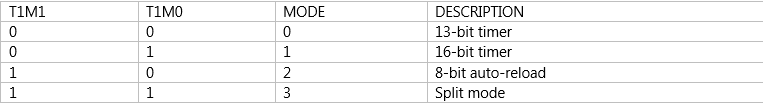
- T1M1,T1M0 These two bits select the operational mode of the Timer 1.
GATE0 enables and disables Timer 1 using a signal brought to the INT0 pin (P3.2):
- 1 - Timer 0 operates only if the INT0 bit is set.
- 0 - Timer 0 operates regardless of the logic state of the INT0 bit.
- C/T0 selects pulses to be counted up by the timer/counter 0:
- 1 - Timer counts pulses brought to the T0 pin (P3.4).
- 0 - Timer counts pulses from internal oscillator.
- T0M1,T0M0 These two bits select the oprtaional mode of the Timer 0.

Timer Control (TCON) Register
TCON register is also one of the registers whose bits are directly in control of timer operation.
Only 4 bits of this register are used for this purpose, while rest of them is used for interrupt control to be discussed later.
TCON register is also one of the registers whose bits are directly in control of timer operation.
Only 4 bits of this register are used for this purpose, while rest of them is used for interrupt control to be discussed later.
- TF1 bit is automatically set on the Timer 1 overflow.
- TR1 bit enables the Timer 1.
- 1 - Timer 1 is enabled.
- 0 - Timer 1 is disabled.
- TF0 bit is automatically set on the Timer 0 overflow.
- TR0 bit enables the timer 0.
- 1 - Timer 0 is enabled.
- 0 - Timer 0 is disabled.
Serial Communication using 8051

UART (Universal Asynchronous Receiver and Transmitter)
One of the microcontroller features making it so powerful is an integrated UART, better known as a serial port. It is a full-duplex port, thus being able to transmit and receive data simultaneously and at different baud rates. Without it, serial data send and receive would be an enormously complicated part of the program in which the pin state is constantly changed and checked at regular intervals. When using UART, all the programmer has to do is to simply select serial port mode and baud rate. When it's done, serial data transmit is nothing but writing to the SBUF register, while data receive represents reading the same register. The microcontroller takes care of not making any error during data transmission.
SBUF
Serial Port Control (SCON) Register
One of the microcontroller features making it so powerful is an integrated UART, better known as a serial port. It is a full-duplex port, thus being able to transmit and receive data simultaneously and at different baud rates. Without it, serial data send and receive would be an enormously complicated part of the program in which the pin state is constantly changed and checked at regular intervals. When using UART, all the programmer has to do is to simply select serial port mode and baud rate. When it's done, serial data transmit is nothing but writing to the SBUF register, while data receive represents reading the same register. The microcontroller takes care of not making any error during data transmission.
SBUF
- It is the serial data buffer.
- When you want to transmit in serial mode write 8bit data here.
- It will get transmitted serially in Txd.
- When 8051 receives serial data in Rxd , it assembles and put the 8bit data here for reading.
Serial Port Control (SCON) Register
- SM0 - Serial port mode bit 0 is used for serial port mode selection.
- SM1 - Serial port mode bit 1.
- SM2 - Serial port mode 2 bit, also known as multiprocessor communication enable bit. When set, it enables multiprocessor communication in mode 2 and 3, and eventually mode 1. It should be cleared in mode 0.
- REN - Reception Enable bit enables serial reception when set. When cleared, serial reception is disabled.
- TB8 - Transmitter bit 8. Since all registers are 8-bit wide, this bit solves the problem of transmiting the 9th bit in modes 2 and 3. It is set to transmit a logic 1 in the 9th bit.
- RB8 - Receiver bit 8 or the 9th bit received in modes 2 and 3. Cleared by hardware if 9th bit received is a logic 0. Set by hardware if 9th bit received is a logic 1.
- TI - Transmit Interrupt flag is automatically set at the moment the last bit of one byte is sent. It's a signal to the processor that the line is available for a new byte transmite. It must be cleared from within the software.
- RI - Receive Interrupt flag is automatically set upon one byte receive. It signals that byte is received and should be read quickly prior to being replaced by a new data. This bit is also cleared from within the software.