CATHODE RAY OSCILLOSCOPE
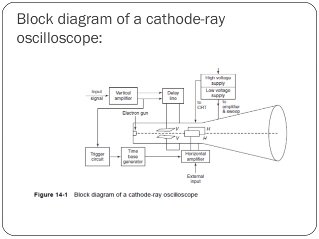
CRO is an extremely useful and versatile laboratory instrument used for the measurement
and analysis of waveforms and other phenomena in electronic circuits. These are basically very fast x - y plotters that display input signal versus another signal. For X-Y plotter, stylus is main part. In the same way for CRO, the luminous spot of the electron beam acts as a stylus that moves over the display area in a response to input voltages. The major subsystem of a general purpose CRO consists of the following
1. Cathode ray tube
2. Vertical amplifier
3. Delay line
4. Time base circuit
5. Horizontal amplifier
6. Trigger circuit
7. Power supply.
Functions of the components:
1. Cathode Ray Tube
It is the heart of the oscilloscope. When the electrons emitted by the electron gun strikes the phosphor screen of the CRT, a visual signal is displayed on the CRT.
2. Vertical Amplifier
The input signals are amplified by the vertical amplifier. Usually, the vertical amplifier is a wide band amplifier which passes the entire band of frequencies.
3. Delay Line
As the name suggests that, this circuit is used to, delay the signal for a period of time in the vertical section of CRT. The input signal is not applied directly to the vertical plates because the part of the signal gets lost, when the delay Time not used. Therefore, the input signal is delayed by a period of time.
4. Time Base Circuit
Time base circuit uses a uni junction transistor, which is used to produce the sweep. The saw tooth voltage produced by the time base circuit is required to deflect the beam in the horizontal section. The spot is deflected by the saw tooth voltage at a constant time dependent rate.
5. Horizontal Amplifier
The saw tooth voltage produce by the time base circuit is amplified by the horizontal amplifier before it is applied to horizontal deflection plates.
6. Trigger Circuit
The signals which are used to activate the trigger circuit are converted to trigger pulses for the precision sweep operation whose amplitude is uniform. Hence input signal and the sweep frequency can be synchronized.
7. Power supply:
The voltages require by CRT, horizontal amplifier and vertical amplifier are provided by the power supply block. Power supply block of oscilloscope is classified in to two types
(1) Negative high voltage supply
(2) Positive low voltage supply
The voltages of negative high voltage supply is from -1000V to -1500V.
The range of positive voltage supply is from 300V to 400V.
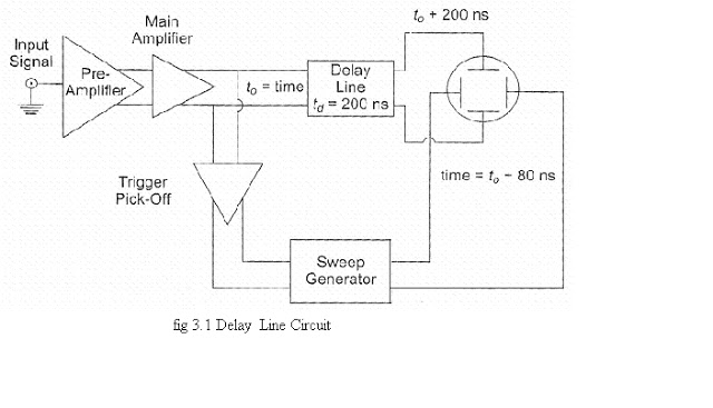
FUNCTION OF DELAY LINE
· The diagram shows that when the delay line is not used, the initial part of the signal is lost and only part of the signal is displayed.
· To counteract this disadvantage the signal is not applied directly to the vertical plates but is passed through a delay line circuit, as shown.
· This gives time for the sweep to start at the horizontal plates before the signal has reached the vertical plates.
· The trigger pulse is picked off at a time t0 after the signal has passed through the main amplifier.
· The sweep generator delivers the sweep to the horizontal amplifier and the sweep
starts at the HDP at time t0 + 80 ns.
· Hence the sweep starts well in time, since the signal arrives at the VDP at time t0 + 200 ns
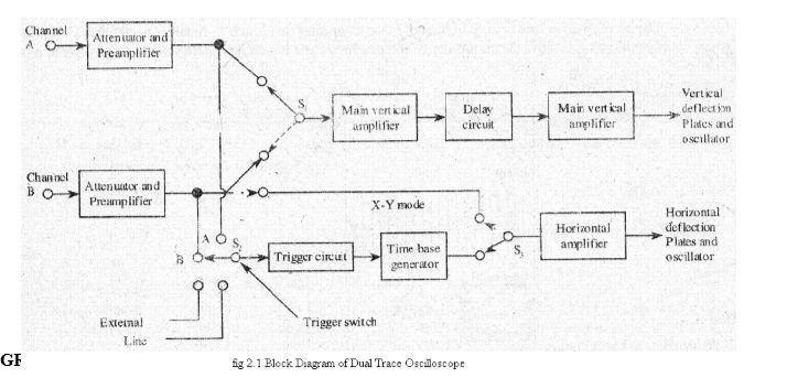
DUAL TRACE CRO
· Two different input signals are used ie Channels A & B with attenuators and preamplifiers.A delay line is used between electronic switch & vertical amplifier that alternately connects the input to main vertical amplifiers.There are two common operating mode for electronic switch called as
1. Alternate mode
In this mode,the CRO spot traces channel A signal on one sweep & channel B on next.These signals have calibrated input attenuators and vertical position control and also amplitude of these signals can be adjusted individually and two images are placed separately on the screen.
2. Chop mode
This mode is used for higher frequencies,say of order 100kHz
to 500kHz.In this mode,the switch connects small segments of A & B waveform to main amplifier at a fast chopping rate of 500kHz ie equal to 1microsecond sweep of each waveform is fed to CRT for display.
· From figure,the switch S2 allows the circuit to be triggered on either of the inputs A or B channel or on line frequency or an external signal
· The horizontal amplifier can be fed from sweep generator or through channel B via switch S1.If channel B,it is called X-Y mode
· In X-Y mode,the oscilloscope operates from channel A to vertical amplifier and the other vice versa
· Several output modes can be selected from front panel of CRO.
Advantages of Dual Beam for Multiple Trace Oscilloscopes
1. A multiple trace oscilloscope making use of dual beam provides a simultaneous display of the two input waveforms on the CRO screen. Hence dual beam CRO is used to compare one signal with another signal.
2. It can capture two fast transient events.
3. It also provides a continuous display of the signals, whereas the display of the two signals
provided by a dual trace oscilloscope consists of small gaps in the trace.
4. It has two separate vertical channels for two input signals.
5. It can also have two separate time base circuits (i.e. horizontal deflection systems). Hence, in dual beam CRO two input signals can be swept horizontally at different rates. Due to this feature, a fast signal can be graphically compared with a slow signal simultaneously on the CRO screen.
Advantages of General Purpose Oscilloscope
1. It provides a graphical display of the amplitude of a signal as a function of time. Hence, it is
used to measure various electrical parameters.
2. Amplitude of signals like voltage, current, power etc., can be measured by the oscilloscope.
3. Apart from amplitude measurement, it can measure frequency, phase angle, time delay of the
signal, time between two events, and relative timing of two related signals.
4. It has an advantage over electro-mechanical measuring devices that it can respond very well
to high frequency signals because it is completely an electronic device.
5. General purpose CRO's are used for maintenance of electronic equipment and laboratory
work.
6. It can also be used to measure capacitance, inductance, etc
CURRENT MEASUREMENT USING CRO
The voltage drop (V) across a resistor 'P' is measured using CRO. The current'!' through the resistor can be determined using the formula I = V / R.
FREQUENCY MEASUREMENT
By observing the A.C. signal waveform on CRO, the number of divisions are measured, on the Timescale. Time 'T' is determined by multiplying No. of divisions with m.sec (or)..t sec) / Div.
Frequency f = 1/T
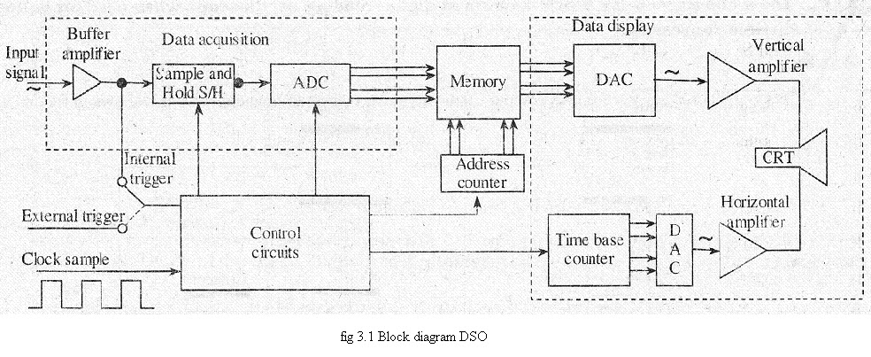
DIGITAL STORAGE OSCILLOSCOPE
· In DSO, the waveform to be stored is digitized, stored in a digital memory and retrieved for display on the storage oscilloscope.
Figure shows the block diagram of DSO as consists of,
1. Data acquisition
2. Storage
3. Data display.
Data acquisition is earned out with the help of both analog to digital and digital to analog converters, which is used for digitizing, storing and displaying analog waveforms. Overall operation is controlled by control circuit which is usually consists of microprocessor.
Data acquisition portion of the system consist of a Sample-and-Hold (S/H) circuit and an analog to digital converter (ADC) which continuously samples and digitizes the input signal at a rate determined by the sample clock and transmit the digitized data to memory for storage. The control circuit determines whether the successive data points are stored in successive memory location or not, which is done by continuously updating the memories.
When the memory is full, the next data point from the ADC is stored in the first memory location writing over the old data.
The data acquisition and the storage process is continues till the control circuit receive a trigger signal from either the input waveform or an external trigger source. When the triggering occurs, the system stops and enters into the display mode of operation in which all or some part of the memory data is repetitively displayed on the cathode ray tube.
In display operation, two DACs are used which gives horizontal and vertical deflection voltage for the CRT Data from the memory gives the vertical deflection of the electron beam, while the time base counter gives the horizontal deflection in the form of staircase sweep signal.
The screen display consist of discrete dots representing the various data points but the number of dot is very large as 1000 or more that they tend to blend together and appear to be a smooth continuous waveform.
The display operation ends when the operator presses a front-panel button and commands the digital storage oscilloscope to begin a new data acquisition cycle
Advantages :-
- Allows for automation.
- In this, slow traces like the temperature variation across a day can be recorded
- With colour Bigger and brighter display, to distinguish multiple traces
- peak detection
