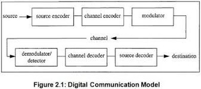
DIGITAL COMMUNICATION SYSTEM
SOURCE ENCODER / DECODER:
The Source encoder ( or Source coder) converts the input i.e. symbol sequence into a binary sequence of 0’s and 1’s by assigning code words to the symbols in the input sequence. For eg. :If a source set is having hundred symbols, then the number of bits used to represent each symbol will be 7 because 27 =128 unique combinations are available. The important parameters of a source encoder are block size, code word lengths, average data rate and the efficiency of the coder (i.e. actual output data rate compared to the minimum achievable rate).
At the receiver, the source decoder converts the binary output of the channel decoder into a symbol sequence. The decoder for a system using fixed length codeword is quite simple, but the decoder for a system using variable length code words will be very complex.
Aim of the source coding is to remove the redundancy in the transmitting
Information, so that bandwidth required for transmission is minimized. Based on the probability of the symbol code word is assigned. Higher the probability, shorter is the codeword.
Ex: Huffman coding.
CHANNEL ENCODER / DECODER:
Error control is accomplished by the channel coding operation that consists of systematically adding extra bits to the output of the source coder. These extra bits do not convey any information but helps the receiver to detect and / or correct some of the errors in the information bearing bits.
There are two methods of channel coding:
1. Block Coding:
The encoder takes a block of ‘k’ information bits from the source
Encoder and adds ‘r’ error control bits, where ‘r’ is dependent on ‘k’ and error control capabilities desired.
2. Convolution Coding:
The information bearing message stream is encoded in a continuous
Fashion by continuously interleaving information bits and error control bits.
The Channel decoder recovers the information bearing bits from the coded binary stream.Error detection and possible correction is also performed by the channel decoder.
The important parameters of coder / decoder are:
Method of coding, efficiency, error control capabilities and complexity of the circuit.
MODULATOR:
The Modulator converts the input bit stream into an electrical waveform suitable for transmission over the communication channel. Modulator can be effectively used to minimize the effects of channel noise, to match the frequency spectrum of transmitted signal with channel characteristics, to provide the capability to multiplex many signals.
DEMODULATOR:
The extraction of the message from the information bearing waveform produced by the modulation is accomplished by the demodulator. The output of the demodulator is bit stream. The important parameter is the method of demodulation.
CHANNEL:
The Channel provides the electrical connection between the source and
Destination. The different channels are: Pair of wires, Coaxial cable, Optical fibre, Radio channel, Satellite channel or combination of any of these.
The communication channels have only finite Bandwidth, non-ideal frequency response, the signal often suffers amplitude and phase distortion as it travels over the channel. Also, the signal power decreases due to the attenuation of the channel. The signal is corrupted by unwanted, unpredictable electrical signals referred to as noise.
The important parameters of the channel are Signal to Noise power Ratio (SNR), usable bandwidth, amplitude and phase response and the statistical properties of noise.
Advantages of Digital Communication:
1. The effect of distortion, noise and interference is less in a digital communication system. This is because the disturbance must be large enough to change the pulse from one state to the other.
2. Regenerative repeaters can be used at fixed distance along the link, to identify and regenerate a pulse before it is degraded to an ambiguous state.
3. Digital circuits are more reliable and cheaper compared to analog circuits.
4. The Hardware implementation is more flexible than analog hardware because of the use of microprocessors, VLSI chips etc.
5. Signal processing functions like encryption, compression can be employed to maintain the secrecy of the information.
6. Error detecting and Error correcting codes improve the system performance by reducing the probability of error.
7. Combining digital signals using TDM is simpler than combining analog signals using FDM. The different types of signals such as data, telephone, TV can be treated as identical signals in transmission and switching in a digital communication system.
8. We can avoid signal jamming using spread spectrum technique.
Disadvantages of Digital Communication:
1. Large System Bandwidth:
Digital transmission requires a large system bandwidth to communicate the same information in a digital format as compared to analog format.
2. System Synchronization:
Digital detection requires system synchronization whereas the analog signals generally have no such requirement
