Interrupts using 8051
IE Register (Interrupt Enable)
It is not possible to forseen when an interrupt request will arrive. If several interrupts are enabled, it may happen that while one of them is in progress, another one is requested. In order that the microcontroller knows whether to continue operation or meet a new interrupt request, there is a priority list instructing it what to do.
The priority list offers 3 levels of interrupt priority:
- EA - global interrupt enable/disable:
- 0 - disables all interrupt requests.
- 1 - enables all individual interrupt requests.
- ES - enables or disables serial interrupt:
- 0 - UART system cannot generate an interrupt.
- 1 - UART system enables an interrupt.
- ET1 - bit enables or disables Timer 1 interrupt:
- 0 - Timer 1 cannot generate an interrupt.
- 1 - Timer 1 enables an interrupt.
- EX1 - bit enables or disables external 1 interrupt:
- 0 - change of the pin INT0 logic state cannot generate an interrupt.
- 1 - enables an external interrupt on the pin INT0 state change.
- ET0 - bit enables or disables timer 0 interrupt:
- 0 - Timer 0 cannot generate an interrupt.
- 1 - enables timer 0 interrupt.
- EX0 - bit enables or disables external 0 interrupt:
- 0 - change of the INT1 pin logic state cannot generate an interrupt.
- 1 - enables an external interrupt on the pin INT1 state change.
It is not possible to forseen when an interrupt request will arrive. If several interrupts are enabled, it may happen that while one of them is in progress, another one is requested. In order that the microcontroller knows whether to continue operation or meet a new interrupt request, there is a priority list instructing it what to do.
The priority list offers 3 levels of interrupt priority:
- Reset! The apsolute master. When a reset request arrives, everything is stopped and the microcontroller restarts.
- Interrupt priority 1 can be disabled by Reset only.
- Interrupt priority 0 can be disabled by both Reset and interrupt priority 1.
- If an interrupt of higher priority arrives while an interrupt is in progress, it will be immediately stopped and the higher priority interrupt will be executed first.
- If two interrupt requests, at different priority levels, arrive at the same time then the higher priority interrupt is serviced first.
- If the both interrupt requests, at the same priority level, occur one after another, the one which came later has to wait until routine being in progress ends.
- If two interrupt requests of equal priority arrive at the same time then the interrupt to be serviced is selected according to the following priority list:
- External interrupt INT0
- Timer 0 interrupt
- External Interrupt INT1
- Timer 1 interrupt
- Serial Communication Interrupt

IP Register (Interrupt Priority)
The IP register bits specify the priority level of each interrupt (high or low priority).
- PS - Serial Port Interrupt priority bit
- Priority 0
- Priority 1
- PT1 - Timer 1 interrupt priority
- Priority 0
- Priority 1
- PX1 - External Interrupt INT1 priority
- Priority 0
- Priority 1
- PT0 - Timer 0 Interrupt Priority
- Priority 0
- Priority 1
- PX0 - External Interrupt INT0 Priority
- Priority 0
- Priority 1
When an interrupt request arrives the following occurs:
- Instruction in progress is ended.
- The address of the next instruction to execute is pushed on the stack.
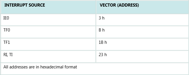
- Depending on which interrupt is requested, one of 5 vectors (addresses) is written to the program counter in accordance to the table below:
- These addresses store appropriate subroutines processing interrupts. Instead of them, there are usually jump instructions specifying locations on which these subroutines reside.
- When an interrupt routine is executed, the address of the next instruction to execute is poped from the stack to the program counter and interrupted program resumes operation from where it left off.
Power Consumption Control
There are two power-saving modes of operation: Idle and Power Down.
Idle mode
Upon the IDL bit of the PCON register is set, the microcontroller turns off the greatest power consumer- CPU unit while peripheral units such as serial port, timers and interrupt system continue operating normally consuming 6.5mA. In Idle mode, the state of all registers and I/O ports remains unchanged.
In order to exit the Idle mode and make the microcontroller operate normally, it is necessary to enable and execute any interrupt or reset. It will cause the IDL bit to be automatically cleared and the program resumes operation from instruction having set the IDL bit. It is recommended that first three instructions to execute now are NOP instructions. They don't perform any operation but provide some time for the microcontroller to stabilize and prevents undesired changes on the I/O ports.
Power Down mode
By setting the PD bit of the PCON register from within the program, the microcontroller is set to Power down mode, thus turning off its internal oscillator and reduces power consumption enormously. The microcontroller can operate using only 2V power supply in power- down mode, while a total power consumption is less than 40uA. The only way to get the microcontroller back to normal mode is by reset.
While the microcontroller is in Power Down mode, the state of all SFR registers and I/O ports remains unchanged. By setting it back into the normal mode, the contents of the SFR register is lost, but the content of internal RAM is saved. Reset signal must be long enough, approximately 10mS, to enable stable operation of the quartz oscillator.
PCON register
The purpose of the Register PCON bits is:
- SMOD Baud rate is twice as much higher by setting this bit.
- GF1 General-purpose bit (available for use).
- GF1 General-purpose bit (available for use).
- GF0 General-purpose bit (available for use).
- PD By setting this bit the microcontroller enters the Power Down mode.
- IDL By setting this bit the microcontroller enters the Idle mode.