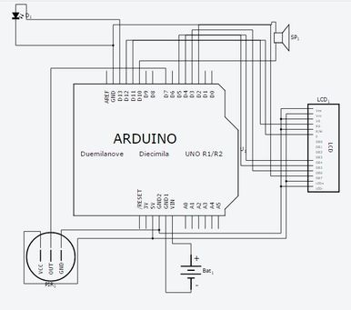
 Introduction We have designed an interesting and cheap home security alarm. This Gadget helps you to protect your house from thieves. In this project I am going to use an Arduino Uno R3 Board, P.I.R Sensor module, LCD and some other components. This Project can either powered with 9V Battery or with U.S.B of your computer. This is a basic motion-sensing alarm that detects when someone enters the area. When an intruder is detected, it activates a siren. Our body generates heat energy in the form of infrared which is invisible to human eyes. But it can be detected by electronic sensor. This type of sensor is made up of crystalline material that is Pyroelectric. In this project, we are using P.I.R. Motion Sensor Module as an infrared sensor that generates electric charge when exposed in heat and sends a signal to Arduino. According to level of the infrared in front of sensor, Arduino displays the status on L.C.D and start buzzing speaker and glows the L.E.D.A simple program is running on Arduino which checks sensor if anything is moved or new object has been detected. You can download the project report from the link below Circuit Diagram Components Required
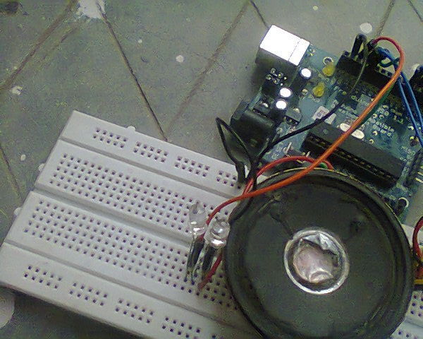
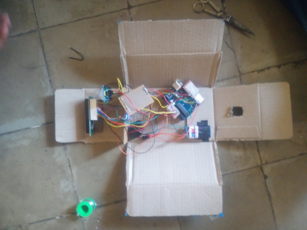
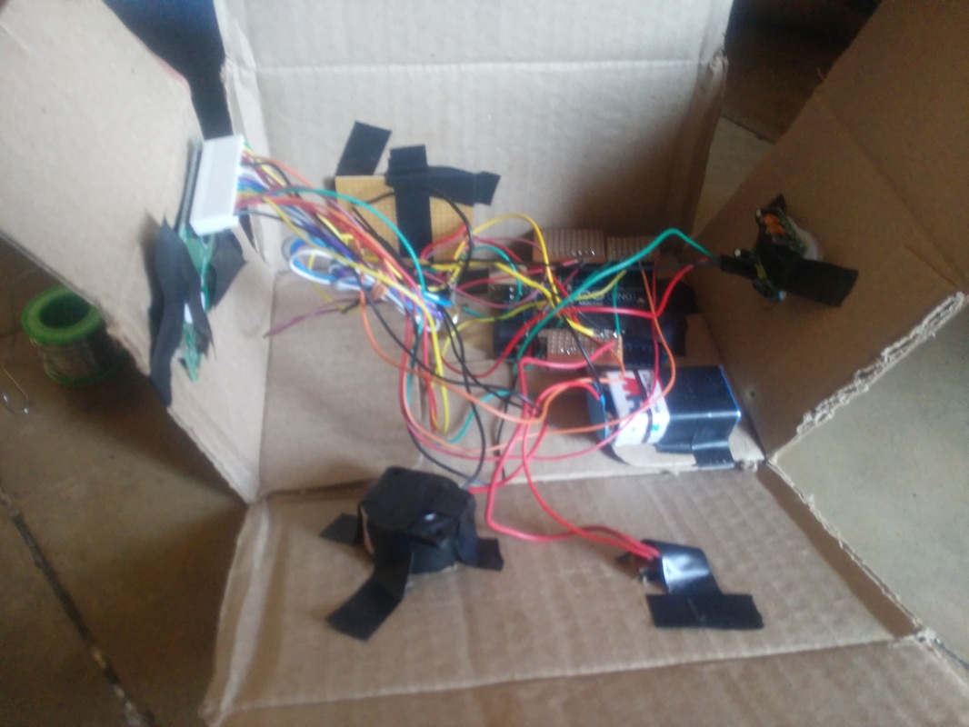
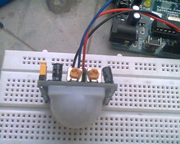
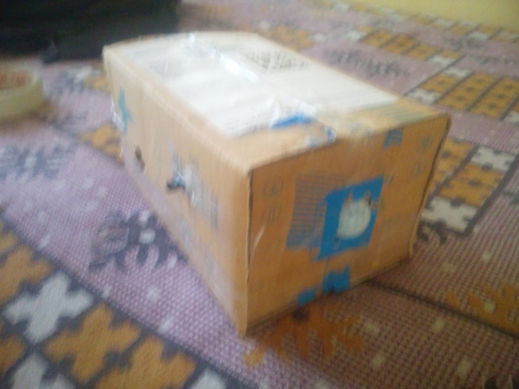
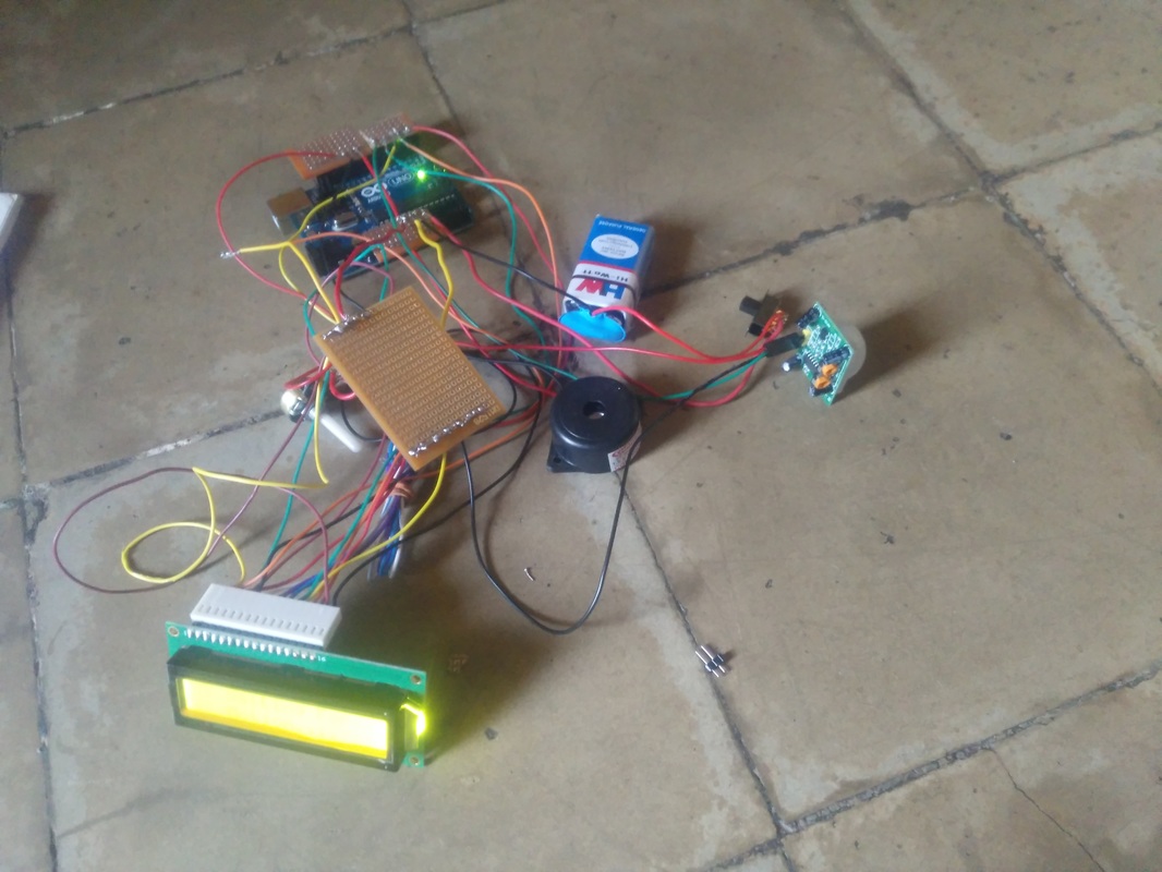
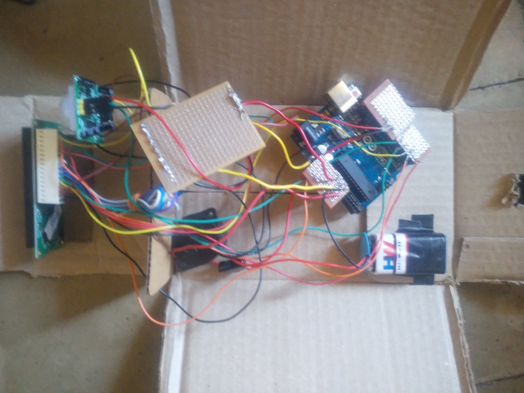
Working This system is a basic motion activated alarm. It is built around an Arduino Microcontroller. It is connected to a PIR motion sensor, a buzzer, a resistor, and a pair of external terminals. The whole system is battery powered so that it is easily portable. Once you have the code, you can connect all the external parts. The easiest way to do this is with a breadboard. This will let you make temporary connections to test everything out. Step 1: Connecting the P.I.R sensor to Arduino.. 1. Connect Vcc pin of P.I.R sensor to positive terminal of Arduino (5V). 2. Connect Gnd pin of P.I.R sensor to any ground pin of Arduino. 3. Connect Out pin of P.I.R sensor to Pin no. -7 of Arduino. Step 2: Connecting L.E.D and Piezo Buzzer To Arduino.. Connecting L.E.D Connect Positive terminal (Longer Lead) Of L.E.D To Arduino Pin no. 13. Connect Negative terminal (Shorter Lead) Of L.E.D To Any Ground Pin. Connecting Piezo Buzzer Connect Positive terminal (Red Wire) Of Buzzer To Arduino Pin no. 10. Connect Negative terminal (Black Wire) Of Buzzer To Any Ground Pin. Step 3: Connecting L.C.D to Arduino To wire your LCD screen to your Arduino, connect the following pins: LCD RS pin to digital pin 12 LCD Enable pin to digital pin 11 LCD D4 pin to digital pin 5 LCD D5 pin to digital pin 4 LCD D6 pin to digital pin 3 LCD D7 pin to digital pin 2 Additionally, wire a 10K pot to +5V and GND, with it's wiper (output) to LCD screens VO pin (pin3). Step 4: Programming Arduino.. 1. Download Arduino IDE 1.0.6 from https://www.arduino.cc/en/main/software. 2. Connect Your Arduino to your computer using USB Cable. 3. Open Arduino IDE, choose your correct board from Tools--Boards 4.Choose Your Correct Port from Tools--Serial Port 6. Copy the following sketch which appears in your Web Browser to your Arduino Sketch Page. 7. Click On Upload Icon or Goto File—Upload Step 5: Drill Holes in the Housing Next we need to drill a few holes in the housing so that we can mount all the parts. Start by using a ¼" hole in one end of the housing. This will be where we mount the buzzer. Then use a ¾" hole saw to drill a hole in the other side of the housing. This will be where we mount the motion sensor Step 6: Glue the Motion Sensor and the Buzzer in Place Apply a small amount of hot glue around the motion sensor where it lines up with the hole in the housing. Then press the motion sensor into the hole. Apply more hot glue around the outside and hold it in place until the glue cools. Then apply a small amount of hot glue to the face of the buzzer. Align the hole in the buzzer with the hole in the housing and press it in place. Hold the buzzer in this position until the glue dries. Step 7: Close Up the Housing The last thing that you need to do is connect the battery and close up the housing. Algorithm
Project code //This Type Of Sensor Detects Motion And lows L.E.D And Start Buzzing,It Also Displays The That The "Motion is Detected" On An Lcd Screen #include <LiquidCrystal.h> int ledPin = 13; // choose the pin for the LED int inputPin = 7; // choose the input pin (for PIR sensor) int pirState = LOW; // we start, assuming no motion detected int val = 0; // variable for reading the pin status int pinSpeaker = 10; //Set up a speaker on a PWM pin (digital 9, 10, or 11) LiquidCrystal lcd(12, 11, 5, 4, 3, 2); // initialize the library with the numbers of the interface pins void setup() { pinMode(ledPin, OUTPUT); // declare LED as output pinMode(inputPin, INPUT); // declare sensor as input pinMode(pinSpeaker, OUTPUT); Serial.begin(9600); lcd.begin(16, 2); lcd.setCursor(2, 0); // Set LCD cursor position (column, row) lcd.print("P.I.R Motion"); // Print text to LCD lcd.setCursor(5, 1); // Set LCD cursor position (column,row) lcd.print("Sensor"); // Print text to LCD delay(4000); // wait 4s // Delay to read text lcd.clear(); // clear LCD display // Clear the display lcd.setCursor(2, 0); // Set LCD cursor position (column, row) lcd.print("Developed By"); // Print text to LCD lcd.setCursor(2, 1); // Set LCD cursor position (column, row) lcd.print("Zishan Ahmad"); // Print text to LCD delay(5000); // Delay to read text lcd.clear(); // Clear LCD lcd.setCursor(0, 0); lcd.print("Processing Data."); delay(3000); lcd.clear(); lcd.setCursor(3, 0); lcd.print("Waiting For"); lcd.setCursor(3, 1); lcd.print("Motion...."); } void loop(){ val = digitalRead(inputPin); // read input value if (val == HIGH) { // check if the input is HIGH digitalWrite(ledPin, HIGH); // turn LED ON playTone(300, 300); delay(150); if (pirState == LOW) { // we have just turned on Serial.println("Motion detected!"); lcd.clear() ; lcd.setCursor(0, 0); // Set LCD cursor position (column 0, row 0) lcd.print("Motion Detected!"); // We only want to print on the output change, not state pirState = HIGH; } } else { digitalWrite(ledPin, LOW); // turn LED OFF playTone(0, 0); delay(300); if (pirState == HIGH){ // we have just turned of Serial.println("Motion ended!"); lcd.clear() ; lcd.setCursor(3, 0); lcd.print("Waiting For"); lcd.setCursor(3, 1); lcd.print("Motion...."); // We only want to print on the output change, not state pirState = LOW; } } } // duration in mSecs, frequency in hertz void playTone(long duration, int freq) { duration *= 1000; int period = (1.0 / freq) * 100000; long elapsed_time = 0; while (elapsed_time < duration) { digitalWrite(pinSpeaker,HIGH); delayMicroseconds(period / 2); digitalWrite(pinSpeaker, LOW); delayMicroseconds(period / 2); elapsed_time += (period); } } You can download the project report from the link below
20 Comments
|
Archives
March 2022
Categories
|
||

 RSS Feed
