Half Adder
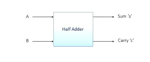
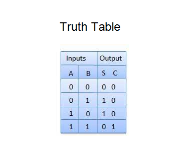
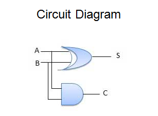
Half adder is a combinational logic circuit with two inputs and two outputs. The half adder circuit is designed to add two single bit binary number A and B. It is the basic building block for addition of two single bit numbers. This circuit has two outputs carry and sum.
Block diagram
Block diagram
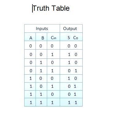
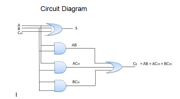
Full Adder
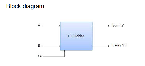
Full adder is developed to overcome the drawback of Half Adder circuit. It can add two one-bit numbers A and B, and carry c. The full adder is a three input and two output combinational circuit.
N-Bit Parallel Adder
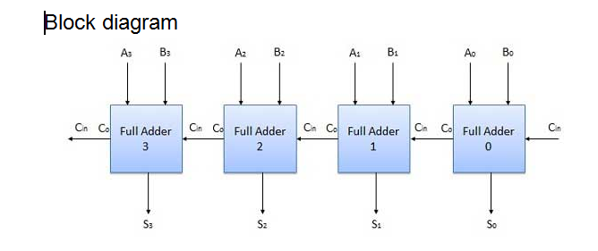
The Full Adder is capable of adding only two single digit binary number along with a carry input. But in practical we need to add binary numbers which are much longer than just one bit. To add two n-bit binary numbers we need to use the n-bit parallel adder. It uses a number of full adders in cascade. The carry output of the previous full adder is connected to carry input of the next full adder.
4 Bit Parallel Adder
In the block diagram, A0 and B0 represent the LSB of the four bit words A and B. Hence Full Adder-0 is the lowest stage. Hence its Cin has been permanently made 0. The rest of the connections are exactly same as those of n-bit parallel adder is shown in fig. The four bit parallel adder is a very common logic circuit.
N-Bit Parallel Subtractor
The subtraction can be carried out by taking the 1's or 2's complement of the number to be subtracted. For example we can perform the subtraction (A-B) by adding either 1's or 2's complement of B to A. That means we can use a binary adder to perform the binary subtraction.
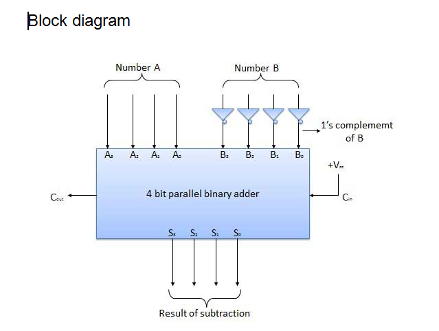
4 Bit Parallel Subtractor
The number to be subtracted (B) is first passed through inverters to obtain its 1's complement. The 4-bit adder then adds A and 2's complement of B to produce the subtraction. S3 S2 S1 S0 represents the result of binary subtraction (A-B) and carry output Cout represents the polarity of the result. If A > B then Cout = 0 and the result of binary form (A-B) then Cout = 1 and the result is in the 2's complement form.
The subtraction can be carried out by taking the 1's or 2's complement of the number to be subtracted. For example we can perform the subtraction (A-B) by adding either 1's or 2's complement of B to A. That means we can use a binary adder to perform the binary subtraction.
4 Bit Parallel Subtractor
The number to be subtracted (B) is first passed through inverters to obtain its 1's complement. The 4-bit adder then adds A and 2's complement of B to produce the subtraction. S3 S2 S1 S0 represents the result of binary subtraction (A-B) and carry output Cout represents the polarity of the result. If A > B then Cout = 0 and the result of binary form (A-B) then Cout = 1 and the result is in the 2's complement form.