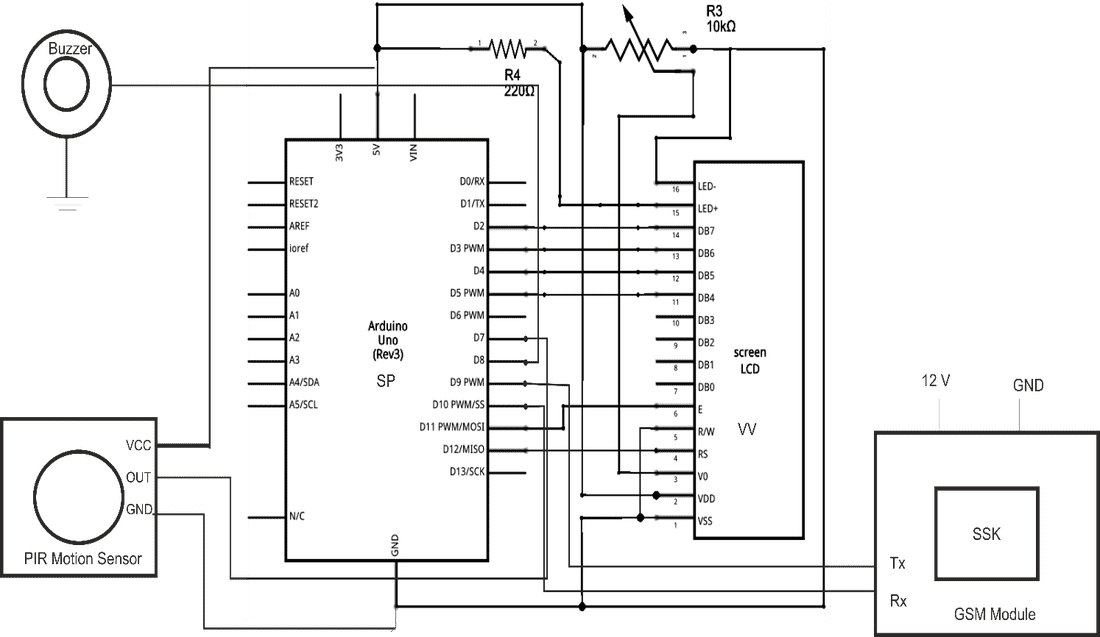
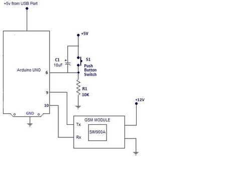
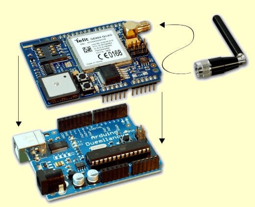
 The need for home security alarm systems nowadays is a serious demand. As the number of crimes are increasing every day, there has to be something that will keep us safe. We are all aware of the high end security systems present in the market but they are not easily available to everyone. We therefore intend to provide a solution by constructing a cost efficient electronic system that has the capability of sensing the motion of the intruders and setting off the alarm along with sending a SMS alert to the user. The basic idea behind this project is that all the bodies generate some heat energy in the form of infrared which is invisible to human eyes. But, it can be detected by electronic motion sensor. The project involves the use of Arduino, motion sensor, buzzer, LCD display, SIM800 GSM module and a simple program. The sensor detect any motion in its permissible range and triggers the alarm. It will also send the signal to Arduino which processes the signal and set off the alarm along with detection message on display and also a SMS is sent to the user as soon as motion is detected. With this system we can easily set up a security alarm in our home for unwanted intruders. COMPONENTS REQUIRED · Arduino Uno · P.I.R Sensor Module · SIM800 GSM module · L.C.D(16 X 2) · 9V/12V Battery · 9V/12V Battery Clip · Casing Box · Piezo Buzzer · Breadboard · Some Jumper Wires · An USB Cable · A Computer WORKING This system is a basic motion activated alarm. It is built around an Arduino Microcontroller. It is connected to a GSM Module, a PIR motion sensor, a buzzer, a resistor, and a pair of external terminals. The whole system is battery powered so that it is easily portable. Once you have the code, you can connect all the external parts. The easiest way to do this is with a breadboard. This will let you make temporary connections to test everything out. Step 1: Connecting the P.I.R sensor to Arduino: 1. Connect Vcc pin of P.I.R sensor to positive terminal of Arduino (5V). 2. Connect Gnd pin of P.I.R sensor to any ground pin of Arduino. 3. Connect out pin of P.I.R sensor to Pin no. -7 of Arduino. 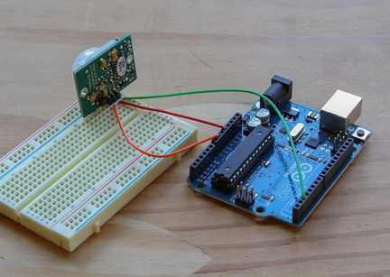 Step 2: Connecting L.E.D and Piezo Buzzer To ArduinoConnecting L.E.D Connect Positive terminal (Longer Lead) Of L.E.D To Arduino Pin no. 13. Connect Negative terminal (Shorter Lead) Of L.E.D To Any Ground Pin. Connecting Piezo Buzzer Connect Positive terminal (Red Wire) Of Buzzer to Arduino Pin no. 8. Connect Negative terminal (Black Wire) Of Buzzer to Any Ground Pin. 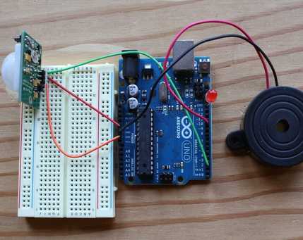 Step 3: Connecting L.C.D to Arduino: To wire your LCD screen to your Arduino, connect the following pins: LCD RS pin to digital pin 12 LCD Enable pin to digital pin 11 LCD D4 pin to digital pin 5 LCD D5 pin to digital pin 4 LCD D6 pin to digital pin 3 LCD D7 pin to digital pin 2 Additionally, wire a 10K pot to +5V and GND, with its wiper (output) to LCD screens VO pin (pin3). 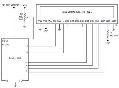 Step 4: Connecting GSM module to Arduino: Connect its Tx pin to Pin 9 of Arduino. Connect Rx to Pin 10 of Arduino. Vcc or Power Jack to +12 Volt. Make GND or Ground pin common to all other components and modules.
Step 5 : Programming Arduino: 1. Download Arduino IDE 1.0.6 from https://www.arduino.cc/en/main/software. 2. Connect Your Arduino to your computer using USB Cable. 3. Open Arduino IDE, choose your correct board from Tools--Boards 4.Choose Your Correct Port from Tools--Serial Port 5. Copy the following sketch which appears in your Web Browser to your Arduino Sketch Page. 6. Click on Upload Icon or go to File—Upload
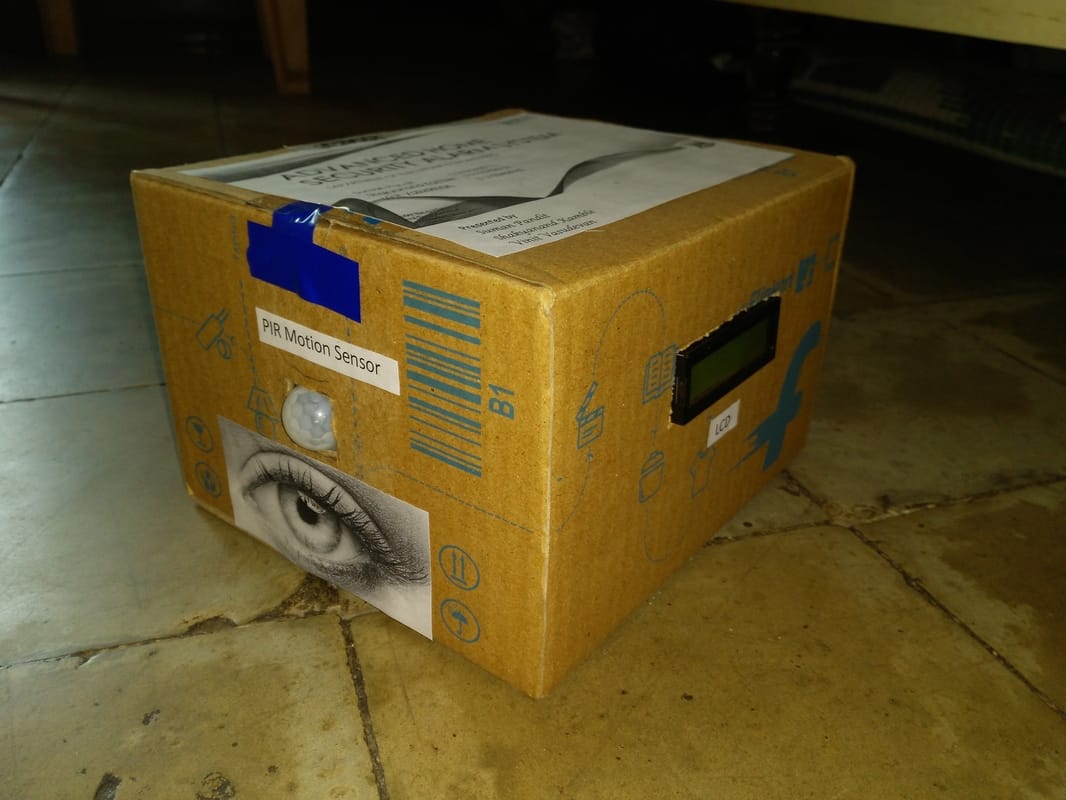
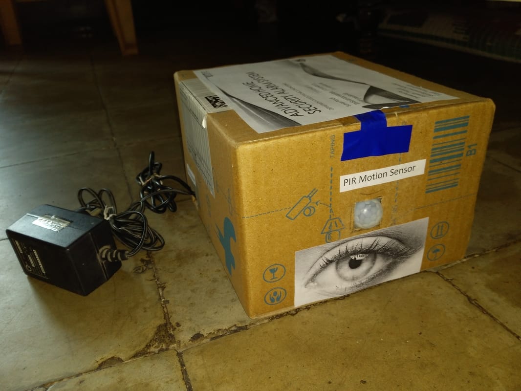
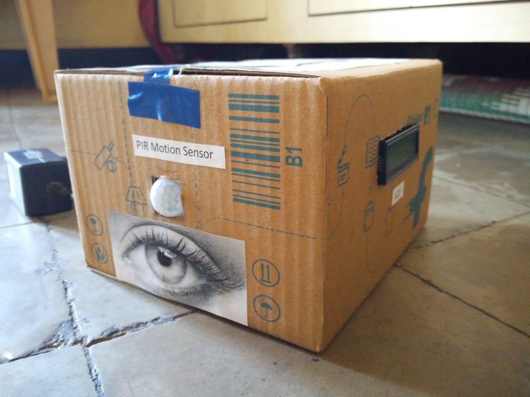
Step 6 : Drill Holes in the Housing: Next we need to drill a few holes in the housing so that we can mount all the parts. Start by using a ¼" hole in one end of the housing. This will be where we mount the buzzer. Then use a ¾" hole saw to drill a hole in the other side of the housing. This will be where we mount the motion sensor Step 7 : Glue the Motion Sensor and the Buzzer in Place Apply a small amount of hot glue around the motion sensor where it lines up with the hole in the housing. Then press the motion sensor into the hole. Apply more hot glue around the outside and hold it in place until the glue cools. Then apply a small amount of hot glue to the face of the buzzer. Align the hole in the buzzer with the hole in the housing and press it in place. Hold the buzzer in this position until the glue dries. The last thing that you need to do is connect the battery and close up the housing. ADVANTAGES
DISADVANTAGES
APPLICATIONS This type of motion sensing alarm system can be easily employable for security purposes at banks, various offices and even for sensitive establishments such as for military. We can easily set up this system for household purposes. The inbuilt SMS system is very essential factor for security purposes and for concerned authorities. APPENDIX Algorithm:
Project code: #include <SoftwareSerial.h> #include<LiquidCrystal.h> LiquidCrystal lcd(12, 11, 5, 4, 3, 2); SoftwareSerial mySerial(9, 10); int sensor=7; //The output of PIR sensor connected to pin 7 int push_switch=6; // push button switch connected to pin 6 int buzzer=8; // buzzer connected at pin 8 int sensor_value; //variable to hold read sensor value int sms_count=0; void setup() { pinMode(sensor,INPUT); // configuring pin 7 as Input pinMode(push_switch,INPUT); // configuring pin 6 as Input pinMode(buzzer,OUTPUT); // configuring pin 8 as OUTPUT mySerial.begin(9600); lcd.begin(16,2); delay(500); lcd.setCursor(2, 0); // Set LCD cursor position (column, row) lcd.print("GSM Security"); // Print text to LCD lcd.setCursor(5, 1); // Set LCD cursor position (column,row) lcd.print("System"); // Print text to LCD delay(4000); // wait 4s // Delay to read text lcd.clear(); // clear LCD display // Clear the display lcd.setCursor(2, 0); // Set LCD cursor position (column, row) lcd.print("Developed By"); // Print text to LCD lcd.setCursor(2, 1); // Set LCD cursor position (column, row) lcd.print("Suman Ssk Vinit"); // Print text to LCD delay(5000); // Delay to read text lcd.clear(); // Clear LCD lcd.setCursor(0, 0); lcd.print("Processing Data."); delay(3000); lcd.clear(); lcd.setCursor(3, 0); lcd.print("Waiting For"); lcd.setCursor(3, 1); lcd.print("Motion...."); } void loop() { Check_Burglar();// subroutine to check sensor status and activation of outputs Check_Reset(); // subroutine to check if alarm reset switch pressed or not } void Check_Burglar() {{sensor_value=digitalRead(sensor); // Reading sensor value from pin 7 if(sensor_value==HIGH) // Checking if PIR sensor sends a HIGH signal to Arduino { digitalWrite(buzzer,HIGH); // Activating the buzzer while(sms_count<3) //Number of SMS Alerts to be sent limited at 3 { SendTextMessage(); // Function to send AT Commands to GSM module } sensor_value=HIGH; lcd.setCursor(0,1); lcd.print("Intruder Alert! SMS sent"); }}} void Check_Reset() { if(digitalRead(push_switch==HIGH))// Checking if pushbutton was pressed { digitalWrite(buzzer,LOW); // turning OFF the buzzer lcd.setCursor(0,1); lcd.print("Alarm OFF!"); sms_count=0; // Reactivating the SMS Alert Facility }} void SendTextMessage() { mySerial.println("AT+CMGF=1"); //To send SMS in Text Mode delay(2000); mySerial.println("AT+CMGS=\"+919544xxxxxx\"\r"); // change to the phone no.to which sms is sent delay(2000); mySerial.println("Intruder detected and alarm initiated!");//the content of the message delay(200); mySerial.println((char)26);//the stopping character delay(5000); mySerial.println("AT+CMGS=\"+919847xxxxxx\"\r"); // change to the phone no.to which sms is sent delay(2000); mySerial.println("Intruder detected and alarm initiated!");//the content of the message delay(200); mySerial.println((char)26);//the message stopping character delay(5000); sms_count++; }
21 Comments
Nezhter Jane Ramos
5/5/2017 09:53:16 am
what algorithm did you use for this study/project? because your study is like our research/thesis proposal, and our problem is ALGORITHM. tnx i hope you will help us. thank you
Yoseph
9/10/2020 03:03:03 am
Could you share me your work (thesis). I am doing this project for my graduation.
AN Singh
31/10/2017 07:12:17 pm
can we add a relay board so that from mobile we can activate /silence a hooter for alerting neighbors when the owner is out of station
rpcc
18/5/2018 06:07:19 pm
Yes, digital output pin for activation and deactivation of relay can be added in the code. That can be added below the line(in code) when sms is being sent. 23/12/2017 04:32:55 pm
Thankyou for this wondrous post, I am happy I watched this site on yippee.
Zohaib
31/1/2018 12:26:34 pm
Hello friends ....I built project same like this but I have trouble I notice this circuit send messages after 1 hour reputedly I can't understand what's wrong any buddy have solution pls its urgent thnx I waite
Shelja Lomash
4/4/2018 11:34:57 am
Please specify the number that should be used in phone and GSM module separately
rpcc
18/5/2018 06:03:41 pm
We should not worry about the number used in GSM module. Both the phone numbers mentioned in code are the numbers in phone on which message is sent.
Rey Manti
22/8/2018 03:41:08 pm
Hello, May I ask. In your diagram I can see a GSM shield. But how can I use the GSM shield here? Because in your diagram and youtube video you show us that you are using GSM module. Please help me.
Ranzel Esber
25/10/2018 12:19:44 pm
This will help me a lot, thanks.... :)
Sohil Jain
23/3/2019 02:44:58 pm
No. Dio apna...please bhai bhauat important he
Md Rafiqul Alam Alif
13/6/2019 03:06:08 am
I am a Bangladeshi.. Do I have to use other GSM modules for Bangladeshi phone numbers?
Johnson
18/9/2019 02:34:17 am
Please can the system be reset by sms in addition to push button? Could you share the code here? Thank you. 19/3/2021 11:22:37 am
I was so happy when I found your blog and I absolutely love your information on the advanced home security system used by Arduino. I liked and it is wonderful to know about so many things that are useful for all of us! Thanks a lot for this amazing blog!!
Jessica
12/7/2022 06:07:35 am
I am really amazed when I saw your blogsite. Full of guides and as a homeowner, I am glad I found you! I want to share a company that provides different varieties of bollards for every need. “First Choice Bollards“. https://firstchoicebollards.com.au/ They have great quality products that suit everyone’s needs with security. Thank you again! 5/1/2023 09:29:09 pm
I am hoping the same best effort from you in the future as well. In fact your creative writing skills has inspired me. 6/2/2023 12:53:25 am
Organic vegan comfort food, along with cocktails & mocktails in an intimate West Village setting. 7/2/2023 11:20:15 pm
Inshot Pro for PC is a revolutionary software that makes editing videos easier, faster and more efficient than ever before. 26/2/2023 03:57:41 pm
We are the most trusted indian satta matka guessing forum, also known as Milan night and day guessing forum updates all sorts of satta matka live results. 9/3/2023 07:47:50 pm
Watch Corp Security is a well-known and well-respected Melbourne event security firm for private or public events in Melbourne. Leave a Reply. |
Archives
March 2022
Categories
|
||||
 RSS Feed
